| |

PRODUCTS
|
|
|
|
|
|
|
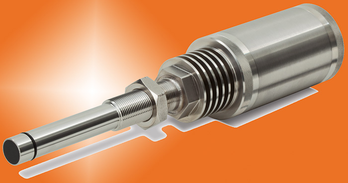
Microwave Solids Flow Monitors -
Models SFD-2 & SFI |
|
 |
Senses Light And Heavy Materials, Small And Large Particles |
|
Non-Contact Sensor Detects Flow Through Most Non-Metallic
Surfaces |
|
Non-Intrusive Flush Mounting. No Probe Protruding Into
Material Flow |
|
SFD-2 Provides Relay Outputs and Convenient Remote
Electronics |
|
SFI Solids Flow Indicator Provides Variable Analog
Signal |
|
Sensors Include CSA Class II, Division I Approval for Hazardous
Locations |
|
|
|
 |
   
|
|
Monitor's line of microwave solids flow monitors
are high quality, industrial grade instruments capable of providing
a signal indicating the flow/no-flow condition of solids and
powders in gravity chutes, feeders and pneumatic pipelines.
The Model SFD-2 Solids Flow Detector provides relay outputs
that can be setup to indicate changes in the target flow stream
(on/off). The Model SFI Solids Flow Indicator provides an analog
output which varies with changing conditions of the material
flow stream. These non-contact monitors contain no moving parts
or probes that can wear out or break off in the material flow,
thus ensuring process integrity.
The SFD-2 and SFI use low
power microwaves to sense motion within the chute or pipeline
being monitored. Microwaves are virtually
unaffected by ambient noise and light, heat, humidity, pressure,
vacuum, high or low temperatures or dust. This provides maximum
effectiveness in typical industrial application environments.
These advantages over sonic or mechanical flow monitors make
microwave technology the best choice for solids flow monitoring.
Similar Item(s):
|
|
Principle of Operation |
 |
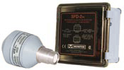
Both the SFD-2 and
SFI utilize a microwave transceiver (combination transmitter/receiver)
enclosed within a watertight, dust-ignition proof powder
coated aluminum housing with a screw-on/off cover. A process
seal (Teflon® or Ryton®) acts as a
transparent window through which the microwave energy is transmitted
and the reflected return signal is received. The transceiver
module generates and transmits a microwave signal into the
area where material flow is to be monitored. The reflected
microwave signal shifts in accordance with the Doppler Effect
phenomena. The Doppler-shifted energy is analyzed to determine
the appropriate output from the unit.
The SFD-2 has a split-architecture
design consisting of the transceiver and a separate power
supply/conditioning circuit board. The relays
are incorporated on the power supply/conditioning circuit board,
which is optionally available with a fiberglass enclosure and
indicating lights. With the SFD-2, the Doppler-shifted energy
signal from the transceiver is carried back to the power supply/conditioning
circuit board through the user-supplied signal and power supply
cable. At the power supply/conditioning circuit board the signal
intensity is indicated with an LED and converted into a relay
output based upon the sensitivity adjustment. The power supply/conditioning
circuit board provides the power to drive the transceiver and
contains the controls for setting sensitivity, hold-off time
delay, hold-on time delay and fail-safe selection.
The SFI
Solids Flow Indicator, unlike the SFD-2, consists solely
of a transceiver. In this case the transceiver will receive
its DC power through the user supplied signal cable and power
supply.
The three-wire design allows the user to monitor the analog
output while providing the supply power to the unit. The
Doppler-shifted
energy is relative to the magnitude of the flow/no-flow condition
that exists, when material velocity is constant, and this
is reflected in the varying analog output signal.
|
|
Applications |
|
|
|
Monitor's Solids Flow Detector and Indicator can
be used in a variety of applications to detect flow/no-flow
conditions of powders and solid materials. The selection of
either SFD-2 Solids Flow Detector or the SFI Solids Flow Indicator
is based upon the type of output required (relay or analog).
|
Detection of a partial or full plug in a conveying line |
|
Detecting the bridging of material in a storage vessel upstream |
|
Sensing inadequate or a lack of flow due to upstream equipment failure (conveyor, blower, diverter valve, feeder) |
|
Verifying flow conditions |
|
Turning on/off equipment or processes downstream |
|
|
Use of SFI Analog Outputt |
|
The Model SFI Solids Flow Indicator can be used to infer the
relative amount of flowing material within the target conduit
(by monitoring the available analog signal). However, it
should be noted that this device provides an output that
should be considered, at best, a very rough estimate of the
flow of material. The analog signal corresponds to the magnitude
of the Doppler-shifted energy created by the flow of material
through the microwave  energy field. energy field.
Note: Monitor Technologies
LLC accepts no responsibility for the accuracy of the analog
output signal. This signal can be
influenced by several varying factors including, but not
limited to, particle size distribution, dielectric constant
variation,
moisture content variation, dispersion of material flow,
variation in velocity of material flow, movement of auxiliary
equipment,
temperature variations and type of conveying system. Please
consult the factory to discuss applications where the accuracy
of the analog output is of importance.
Pictured at the right
is a SFI installed in a plant that manufactures ink for desktop
printers and copy machines. 100-pound batches
of carbon black come out of a feeder and are pneumatically
conveyed through a four-inch vertical line. The SFI is
used to indicate when a batch of carbon black has cleared the
line.
|
|
Features |
|
| TRANSCEIVER
(SENSOR) |
|
Powder
coated NEMA 4 cast aluminum construction
|
|
Approved
for Class II hazardous areas
|
|
Meets
applicable FCC regulations
|
|
Screw-on/off
cover
|
|
Teflon® process
seal is standard
|
|
15-30VDC/Analog
three-wire input/output (SFI only) |
| CIRCUIT
BOARD (SFD-2 ONLY) |
|
Connects
to transceiver using an inexpensive, low voltage 3-wire
system
|
|
Convenient
control functions for time delay, sensitivity and fail-safe
selection
|
|
Control
function changes can be made without accessing the transceiver
|
|
Yellow
and Red LEDs indicate material flow intensity and output
activation |
|
|
Options |
|
RYTON® PROCESS
SEAL
Both the SFD-2 and SFI come standard with a Teflon® process
seal window through which the transmit/receive signal passes.
While this material is compatible with most applications, a Ryton® seal
is available for use in applications where the seal is subjected
to high pressure or abrasive materials.
ENCLOSURE FOR CIRCUIT
BOARD (SFD-2 only)
The standard SFD-2 does not provide
an enclosure for the power supply/conditioning circuit board.
This allows the user to install the board wherever is appropriate.
A NEMA 4X enclosure is available. When selected, the power
supply/conditioning circuit board is supplied installed within
a fiberglass enclosure furnished with long-lasting LED
indicators flush with the enclosure face.
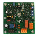 |
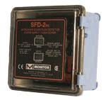 |
Left: Power Supply/Conditioning Circuit Board
Right: Optional Enclosure |
|
|
Accessories |
|
GALVANIZED HALF-COUPLING
Monitor provides a galvanized half-coupling which can be welded
to the chute or pipe for mounting the transceiver. Half Coupling:
P/N 17-3111
LOCKNUT
The optional locknut provides flexibility in the depth of
the mounting of the transceiver to ensure that the process
seal is
flush with the inside of the conduit in which the target material
flows. Lock Nut: P/N 17-3000-7C
SADDLE COUPLING
The saddle coupling provides a means of mounting the transceiver
without welding a mounting coupling. The saddle coupling,
which includes a gasket, is suitable for round chutes 4-10" (102-254mm)
in diameter and can be easily clamped to the chute or pipeline.
Saddle Coupling: P/N 17-3102-1
STAINLESS STEEL ADAPTERS
Four different mounting adapters can be used to provide a
stainless steel process contacting surface. The adapter
can be of either
1-1/2" NPT or Tri-Clamp® food grade construction.
1-1/2" NPT: P/N 17-3303-1 (Teflon® seal) P/N 17-3303-3
(Ryton® seal)
Tri-Clamp: P/N 17-3305-1 (Teflon® seal) P/N 17-3305-3
(Ryton® seal)
|
|
Specifications |
|
| TRANSCEIVER
(SENSOR) |
| Power
Requirement: |
|
SFD-2: |
Provided
by power supply/conditioning PCB |
|
SFI: |
15-30VDC,
100mA max. |
| Enclosure: |
Die-cast
aluminum, beige polyester powder coated |
| Enclosure
Protection: |
NEMA
4, IP66 |
| Ambient
Operating Temperature: |
|
SFD-2: |
-40° to
+185° F (-40° to +85° C) |
|
SFI: |
-13° to
+185� F (-25� to +85� C) |
| Process
Temp. Max: |
250°F
(121°C) if ambient air temp. below 150°F
(65°C) |
| Process
Seals: |
TFE
Teflon®, Ryton® |
| Pressure
Ratings: |
TFE
Teflon® (75 PSI intm), Ryton® (300 PSI) |
| Process
Connection: |
1
1/4" NPT (1-1/2” w/ SS Adapter) |
| Conduit
Connection: |
(2)
1/2" NPT |
| Detection
Range: |
0
to 10' free air, env. and target dependent |
| Sensitivity: |
Switch
selectable HI/LOW |
| Minimum
Velocity: |
2.5
ft/sec (762mm/sec) |
| Output: |
|
SFD-2: |
None,
signal from transceiver is delivered to and processed
by power supply/conditioning circuit board |
|
SFI: |
4-20mA
output typical (full span may not be achieved; actual
span is application dependent) |
| Isolation
(SFI Only): |
750
VPK isolation between sensor ground and user power
supply/analog supply |
| Indicators: |
Green
LED – power; Yellow LED Ðloop, intensifies
with disturbance detected |
| Emission: |
24.125
GHz, FCC & IC certified, energy levels less than
1mW/cm(2) (OSHA limit at 10mW/cm(2)) |
| Approvals: |
CSA(us/c),
Class II Div. 1 & 2 Groups E, F & G
CE Mark (Ordinary
Location) |
| POWER
SUPPLY/ CONDITIONER BOARD (SFD-2 ONLY) |
| Enclosure
(if supplied): |
PBT/Polycarbonate |
| Enclosure
Protection: |
NEMA
4X, IP66 |
| Ambient
Operating Temperature: |
-40°F
to 158°F (-40°C to 70°C) |
| Interconnection
Distance: |
2500ft
max (minimum wire size 22 AWG) |
| Power: |
Universal 100-240 VAC, + 10%, 50/60 HZ |
| Power
Consumption: |
5
VA max |
| Output: |
DPDT
dry contact, 5A @ 240VAC, 30 VDC |
| External
lights (if applicable): |
Solid
state LED clusters
Yellow – material sense; Red – output
operate |
| Sensitivity
Adjustment: |
Single-turn
adjust 0 to 100% of sensor range |
| Time
Delay: |
Hold-off,
single-turn adjustment, 0.25 to 15 sec.
Hold-on, single-turn adjustment, 0.25 to 15 sec. |
| Fail-Safe: |
Switch
selectable, (Flow/No-Flow) |
| Indicators: |
Green
LED - power; Yellow LED - sense; Red LED - output |
| Approvals: |
CSA(us/c),
ordinary locations, industrial control equipment
CE Mark (ordinary locations) |
|
Ryton® -
Trademark of Phillips Chemical Co.
Teflon® - Trademark of Dupont Chemical Co.
Tri-Clamp® - Trademark of Tri-Clover, Inc.
|
|
Warranty |
|
Monitor
Technologies LLC warrants each SFD-2/SFI it
manufactures to be free from defects in material and workmanship
under normal use and service within two (2) years from the
date of purchase. The purchaser must give notice of any defect
to Monitor within the warranty period, return the product
intact and prepay transportation charges. The obligation
of Monitor Technologies LLC under this warranty is limited
to repair or replacement at its factory. This warranty shall
not apply to any product which is repaired or altered outside
of the Monitor Technologies LLC factory, or which has been
subject to misuse, negligence, accident, incorrect wiring
by others or improper installation. Monitor Technologies
LLC reserves the right to change the design and/or specifications
without prior notice.
|
|
Part
Numbers / Product Configurations |
|
Part
# > Product Configuration
SFD-2
17-8411-1 SFD-2,TEFLON®,SENSOR ONLY
17-8411-11 SFD-2,TEFLON®,w/PS/COND PCB
17-8411-12 SFD-2,TEFLON®,w/PS/COND ENCL.& LIGHTS
17-8411-2 SFD-2,RYTON®EQUIV.),SENSOR ONLY
17-8411-21 SFD-2,RYTON®(EQUIV.),w/PS/COND PCB
17-8411-22 SFD-2,RYTON®(EQUIV.),w/PS/COND ENCL.& LIGHTS
SFI
17-8511-11 SFI,TEFLON®,4-20mA
17-8511-21 SFI,RYTON®(EQUIV.),4-20mA |
|
Last Rev.: December, 2019 |
|
|
|
|
 |
|
 |
|
QuantiMassTM
Mass Flow Measurement Systems |
The QuantiMass in-line mass flow sensor measures the flow of quantities in pneumatic conveying & free-falling processes. The sensor is based on the latest Microwave Doppler Effect technology and provides fast, in-line / on-line measuring without the use of weight scales.
The sturdy, non-intrusive design of the sensor minimizes maintenance. In addition, the compact size of the sensor makes for easy installation into existing processes. Suitable for powders, dust, pellets, and granular up to 0.75 inch (2cm).
Versions:
Ultra Series-Includes controller
PRO Series-Includes transmitter
A practical application for the QuantiMass would be to monitor material flow rates to verify blending mixture ratios.
Principle of Operation:
The QuantiMass Mass Flow Measurement Sensor / Meter is designed with the latest microwave technology and is used to continuously quantify the flow of powders & solids being conveyed in metallic pipes. The QuantiMass is based on technology that has been developed and proven over several years. The measurement process of the sensor is centered on the Doppler effect. The mass flow-rate is determined by evaluating the frequency and amplitude changes during the measurement process. Particles at rest, such as deposits, do not influence the measurement. All powders, dust, pellets and granules can be measured reproducibly, up to the size of 0.75 inch (2cm). The QuantiMass sensor is suitable for continuous in-line / on-line measurements in pneumatic conveying or in free-fall pipelines.
Click
here for more information on the QuantiMass
or
contact Monitor Technologies LLC at
Tel.: 800-601-6319 in the USA and
Tel.: 630-365-9403
worldwide.
|
 |
|
|
|
|
|
|
|
 |
|
 |
 |
|