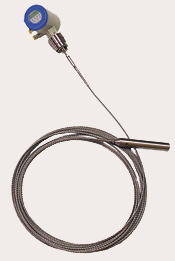

FLEXAR® GUIDED WAVE RADAR Level Sensor

|
|
|
|
|
|
|
|
|
|
|
|
|
|
|
|
Similar Item(s):
 |
 |
| RadarRight(TM) Non-Contact Continuous Level Sensor | SiloPatrol® Continuous Level Sensor |
Principle of Operation
Flexar® smart guided wave radar level sensors and transmitters operate using TDR (time domain reflectometry) principles that were first developed in the middle part of the 20th century for use in the geological field. Further development of TDR led to its use in the telecommunication industry for detecting breaks in cables. Flexar technology was pioneered in the mid-late 1990’s when TDR was applied to level measuring applications within the process measurement industry.
In the application
of TDR for process level measurement micro-pulses are continuously
transmitted along a probe or “wave guide” at
the speed of light. As soon as the pulses reach the material
surface they reflect back to the sensor electronics unit. The
time-of-flight of the pulses is calculated and directly related
to the distance from the point at which the sensor is mounted
on the top of the vessel to the material surface (level). The
output from the electronics is continuously updated as the
level of the material surface changes.
Flexar smart guided wave radar sensors are equipped with two different measuring modes. In the Direct measuring mode the pulses directly reflect off the material surface back to the electronics unit. This mode is used in applications where the material being measured has a dielectric constant as low as 2.1 for single-cable/rod probes and 1.8 for twin-cable probes.
For materials with dielectric
constant below the above mentioned limits, down to as low
as 1.4, the second measurement mode
is used. This is the TBF (tank bottom following) mode, which
is
used due to the inability of the pulses to adequately reflect
off of the surface of very low dielectric materials. In this
measuring mode the Flexar sensor has a “short circuit” at
the bottom of the probe at a precisely known distance from
the sensor’s mounting point. 
In the TBF mode the pulses travel through air at the speed of light and then pass through the material in the vessel at a slower speed, dependent on the specific dielectric constant. The pulses are reflected at the short circuit back up the probe. Flexar sensors in the TBF mode measure the time between the emission and reception of the pulses from the probe short circuit. Because the return time of a pulse when no material is present (through air) is known, we can determine the difference in time between the time-of-flight when empty and the time-of-flight when filled as being directly proportional to the material level in the vessel.
Applications
The Flexar® smart guided wave radar continuous level measuring system can be used in a wide variety of applications, including powders, coarse/fine granular solids, liquids, foodstuffs and even some corrosive substances. Flexar sensor technology is proven in many difficult applications including those where dust levels make it difficult for other technologies to perform reliably, especially at long ranges.
Please consult Monitor's Technical Support Dept. to verify that the Flexar is the best fit for your specific application. Certain conditions (like target material dielectric, silo height, etc.) need to be taken into consideration.
Typical Applications include, but are not limited to: |
||
Feeds |
Cement |
Bulk Chemicals |
Grains |
Aggregates |
Oils |
Carbon Black |
Coal Dust |
Some Liquids |
Fly Ash |
Silica |
Lime |
Powders |
PVC Powder |
Flour |
Pellets |
||

The maximum range for solids applications
is limited to 100ft (30m) due to load limits possible from
heavy materials
in long
ranges. Liquid applications can extend up to 200ft (60m).
Any application requiring a continuous level measurement
update
where the process temperature does not exceed 392° F (200°C)
and 580psig
(40bar) is possible. The 316 stainless steel probes and threaded
or flanged process connections make the Flexar continuous
level measuring system ideal for almost any bulk solid and
liquid
application. To ensure a successful and reliable application,
consult with
the Monitor Technologies factory-based technical support
group to see if Flexar is right for your application.
-------------------------------------------------
REMOTE INVENTORY MONITORING
If material levels need to be monitored at one or many locations (i.e. your facility, a location down the street, or a plant on the other side of the world) the Flexar® system can provide accurate and reliable measurements. Using SiloTrack™ Version 3.5 software, inventory monitoring from remote locations has never been easier.

-------------------------------------------------
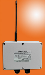
WIRELESS SENSOR COMMUNICATION INTERFACE
Using the available WirelessEZ interface in your application may help you reduce the installed cost of your SiloTrack™ / Flexar® system even further. The WirelessEZ transceivers use frequency-hopping spread-spectrum wireless technology and operate in the FCC license-free 900MHz band. This provides the longest range and most reliable wireless communications available. Working in conjunction with SiloTrack™ PC-Based inventory management software, the WirelessEZ transceivers provide the most functional and economical inventory management system available today.
Click here for more details on the WirelessEZ and contact our technical support personnel today to see if your application can benefit from a wireless communications solution.
-------------------------------------------------
AUXILIARY OUTPUT ENCLOSURES (AOE)
A unique feature of the Flexar® Inventory Management System is the ability to incorporate both relay and analog outputs with a standard "smart" output sensor system. These auxiliary relay and/or analog outputs are provided in Auxiliary Output Enclosures (AOE) and are programmed and controlled by either the HMI2 or SiloTrack™ PC-based Inventory Management Software. One analog output and up to four relays (two for HMI2; four for SiloTrack) can be assigned to each of the “smart” output sensors. These can be used to tie the Inventory Management System into remote control systems, sound alarms and for local control functions. Up to 16 analog outputs or 32 relays can be provided within a single enclosure. Up to four AOE’s can be connected on a single network. The AOE can be located close to the point of hardwiring termination minimizing wiring and installation costs.
2-Card AOE
Features
Solid-State Performance,
No Moving Parts... |
|
Measure Materials
With Dielectric > 1.4
(TBF Mode)... |
|
Unaffected By Dust
And Changes In Material Properties... |
|
Range Of Probes... |
|
Assortment Of Process Connections... |
|
Dual Compartment Enclosure... |
|
Local LCD Display And Setup... |
|
Universal Power Supply... |
|
Choice of outputs... |
|
Remote electronics available... |
|
All units include the CE
mark and are approved for use in ordinary locations. |
Probe Styles
 |
|
Single Cable 0.16” (4mm) |
Single Cable 0.31” (8mm) |
Single flexible 316 SS cable with counterweight |
Single Flexible 316 SS cable with large or small counterweight |
Vessel height < 150ft (45m); Liquids; Some solids |
Vessel height < 100ft (30m);
|
 |
 |
Twin Cable 0.16” (4mm) |
Single Rod 0.38” (10mm) |
Two flexible 316 SS cables with spacers between them at intervals, w/ counterweight |
Single 316 SS rigid rod |
Vessel height < 200ft (60m); Low dielectric liquids, some granules (consult Monitor) |
Vessel height < 10ft (3m); Liquids; Some powders (consult Monitor) |
HMI2 Operator Interface Control Console
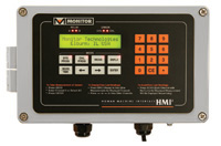
The HMI2 operator interface control console provides convenient, local interface for Monitor’s “Smart” RS-485 SiloPatrol® SMU SE cable-based inventory monitoring sensors and/or Flexar® guided wave radar sensors. HMI2 allows for monitoring up to 32 SMU and/or Flexar sensors. The multi-functional HMI2 controls sensor operations, displays measured and calculated data and performs/displays system and sensor diagnostic messages. The HMI2 is easily programmed to display calculated level, volume, weight or percent in addition to the basic distance measurement. Manual readings are taken by depressing the MEAS button, followed by the channel number, followed by ENTER. The HMI2 can also be programmed to operate the SMU “Smart” RS-485 sensors automatically. Menu options allow the user to select days of SMU operation (such as Mon.-Fri.), time window (such as 7 a.m.-3 p.m.) and measurement interval (minimum 30 minutes).
Click Here for more details on the HMI2
SiloTrack(TM) PC-Based Inventory Management Software
SiloTrack™ Version 3.5 Inventory Management Software provides users with an unsurpassed, flexible graphical interface for SiloPatrol® SE “smart” output sensors. Together, SiloTrack Server and Client software can provide inventory monitoring and management to a virtually unlimited number of users, both internal and external to your facility. This allows easy implementation of remote monitoring and vendor managed inventory programs.
SiloTrack capabilities include:
-
Monitor up to 128 sensors/with up to 5 sensors per vessel
-
Easy to set up and use
-
Network capable
-
Remote monitoring via LAN, Internet/WAN or dial-up
-
Available in English/Spanish language
-
Automatic and manual measurement initiation
-
Curve-fit weight table
-
Enhanced 3-D type silo graphics
-
Export silo history and alarm data
-
Automatic Reports and Scheduling
-
Set up four alarms per silo
-
Alarm notification via e-mail, fax, etc.
Click Here for more details on SiloTrack
Specifications
Power Requirements: |
100-240VAC (+10%/- 15%); 9VA; 50/60Hz
or |
Altitude: |
6562ft (2000m) maximum |
Installation Category: |
II |
Pollution Degree: |
4 (reduced to 2 by enclosure) Suitable for indoor/outdoor use |
Process Temperature: |
|
Ordinary Location Units |
-20°F to +300°F (-30°C to +150°C); |
|
|
Ambient Temperature: |
-5°F to +120°F (-20°C to +50°C) |
Operating Pressure: |
|
1-1/2” NPT |
-14.5psig to +580psig (-1bar to +40bar) |
G 1-1/2 (1-1/2” BSP): |
-14.5psig to +580psig (-1bar to +40bar) |
2” ANSI: |
-14.5 psig to 150 psig (-1bar to 10bar) |
DN50PN40: |
-14.5psig to +580psig (-1bar to +40bar) |
Measurement Range: |
|
Single Cable 0.16” (4mm): |
150ft (45m) |
Single Cable 0.31” (8mm): |
100ft (30m) |
Twin Cable 0.16” (4mm): |
200ft (60m) |
Single Rod .38” (10mm): |
10ft (3m) |
Accuracy: |
|
Direct Mode: Solids |
± 0.8” (20mm) |
Liquids |
< 20ft (6m): ± 0.2” (5mm) |
TBF Mode (All): |
± 0.8” (20mm) when Dielectric is constant |
Repeatability: |
± 0.04” (1mm) |
Resolution: |
± 0.012” (0.3mm) |
Minimum Dielectric Constant: |
|
Direct Mode |
Twin Cable ≥ 1.8; Single Cable/Rod ≥ 2.1 |
TBF Mode |
All Probe Styles ≥ 1.4 |
Process Mounting Connection: |
|
Single Cable/Rod Only |
1-1/2” NPT; G 1-1/2 (1-1/2” BSP) |
All probe Styles |
2” ANSI 150lb. Flange; DN50PN40 Flange |
Conduit/Cable Entry: |
|
NPT/ANSI Process Connections |
(2) 1/2” NPT |
BSP/DN Process Connections |
(2) M20 x 1.5 cable connectors |
Probe Styles: |
|
Single Cable:0.16” (4mm) |
316SS |
Single Cable:0.31” (8mm) |
316SS |
Single Rod |
316SS; 0.38” (10mm) diameter; |
Twin Cable |
316SS; Two 0.16” (4mm) cables; FEP spacers |
Weight: |
|
Enclosure |
18lb (8kg) without probe for ordinary location; |
Single Cable |
0.08lb/ft (0.12kg/m) |
Single Cable 0.31” (8mm) |
0.28lb/ft (0.41kg/m) |
Single Rod |
0.42lb/ft (0.62kg/m) |
Twin Cable |
double weight of 4mm cables above for twin cable |
Maximum Traction Loading: |
|
0.31” (8mm) Single Cable |
7,700lbs/3.9 tons (3.5 metric tons) |
0.16” (4mm) Single Cable |
2250lbs/1.1 tons (1.02 metric tons) |
Minimum Separation From Objects: |
|
Single Cable/Rod |
12” (300mm) |
Twin Cable |
4” (100mm) |
Output Signal: |
|
“Smart”: |
RS-485, half-duplex, isolated, proprietary protocol |
Analog: |
4-20mA; 350ohms maximum load |
Wiring Distance (“smart” output): |
4,000ft (1,220m) |
Local Display: |
3-line; Backlit LCD; 3 pushbuttons; |
Materials of Construction: |
|
Enclosure: |
Aluminumm, powder coated |
Threaded/Flange Connection: |
316 Stainless Steel |
Process Insulator: |
Teflon (PTFE) |
O-Ring Seal: |
Viton |
Probes: |
316 Stainless Steel |
Remote Electronics: |
16.4’ (5m) pre-wired interconnection cable |
Dead Zones: |
|
Single Cable/Rod |
|
Dielectric = 80 (water) |
Top = 15.75” (400mm) |
Dielectric = 2.4 (oil) |
Top = 19.7” (500mm) |
Twin Cable |
|
Dielectric = 80 (water) |
Top = 9.8” (250mm) |
Dielectric = 2.4 (oil) |
Top = 13.0” (330mm) |
Enclosure Rating: |
ENCLOSURE TYPE 4X, IP66 |
Approvals: |
|
Integral Electronics Only |
|
Ordinary Location |
CE Mark |
|
|
Remote Electronics |
|
Ordinary Location |
CE Mark |
Hazardous Location |
|
Teflon® is a registered trademark
of Dupont Chemical Co.
Windows® is a registered trademarks of
the Microsoft Corporation
RSView® is a registered trademark of Rockwell Automation
Wonderware® is a registered trademark of Wonderware Corporation
Intellution® is a registered trademark of Intellution,
Inc.
Cimplicity® is a registered trademark of General Electric
Company
Bluetooth® is a registered trademark of Bluetooth SIG, Inc.
AndroidTM is a trademark of Google Inc.
ModbusTM is a trademark of Schneider Electric / Modicon