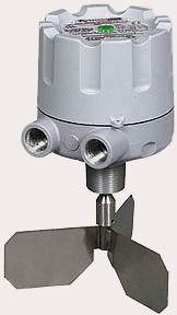

Safepoint® Rotary
Paddle Level Switch

![]()
![]()

|
|
|
|
|
|
|
|
Similar Item(s):
Model KA / KAX Rotary Paddle Level Indicator
Imagine a bin level switch that is more than just an indicator of the presence or absence of material. Picture technology that allows intelligent devices to indicate when something is wrong. Dream that a level sensor provides real-time information when the quality of the sensor function no longer allows it to operate as you expect. That is a “self-validating” bin level indicator. Now you can wake up, your dream has arrived. Costly overfilling and outages due to sensor failure can now be avoided!
Principle of Operation
While the SafePoint level switch is an evolution in rotary paddle technology, it continues to use tried-and-true operating techniques. Unlike many other available units, the SafePoint incorporates a feature that automatically shuts off its motor when the paddle is in a stalled condition. This extends the life of the unit and minimizes maintenance.
The operation of the SafePoint® rotary paddle bin monitor uses patented technology to detect material presence and operational status of the unit. The unit is installed through the wall of the vessel so that the paddle protrudes inside the vessel. A small electric motor drives the paddle, which rotates freely in the absence of material.
The rotation of the unit’s shaft is continuously monitored by detection of a magnetized rotating disk. When the paddle is impeded by material, the shaft rotation stops. The motor rotates within the housing and magnetized sections of the motor mounting plate are detected. Use of these patented magnetic sensing techniques eliminates problems that occur with fouling of the optical systems used by other brands.
The built-in microcontroller performs self-validating diagnostics and monitors both shaft and motor mounting plate rotation. This allows the SafePoint to easily distinguish between material presence and any electrical and mechanical failure of the unit. When material presence is detected, the SENSE relay changes state and the drive motor is de-energized to extend motor life. This output is available to control a process function or alarm circuit. When the material level drops, a tension spring returns the drive motor to its original running condition and is reactivated.
A unit failure is detected by sensing a lack of shaft rotation while material presence has not been detected by rotation of the motor mounting plate. In a failure condition the independent FAULT relay will change state. Monitoring the state of both the SENSE and FAULT relays provides the most flexibility for control and monitoring that is beyond being just “fail-safe”.
Applications
The rugged and reliable fail-safe design of the SafePoint® bin monitor makes it the best choice for critical level control applications. The unit is compatible with many granular, pelletized and powder bulk applications. It can be utilized for high level indication of materials over 10 lb/ft³ (160 kg/m³ ) and for low and intermediate level indication for materials over 5 lb/ft³ (80 kg/m³ ). The SafePoint bin level monitor can be installed almost anywhere dry bulk materials are stored including bins, hoppers, silos and tanks.
Typical Applications include, but are not limited to: |
||
Feed |
Silica Sand |
Rocks |
Pellets |
Wood |
Calcium Dust |
Rubber |
Metals |
Regrind |
Coal |
Peanuts |
Malt |
Clays |
Resin |
Limestone |
Grain |
Foundry Sand |
Pre-Mix Ingredients |
Rawhide |
Sawdust |
Coffee |
Features
|
Self-validating operation monitors electrical and mechanical status for critical applications - beyond "fail-safe" |
|
(1) Use of magnetic sensing technology ensures reliable operation even in dusty environments |
|
(2) Twist on/off cover for convenient and easy access - No bolts to lose or hold |
|
(3) 1-1/4” NPT or 1-1/2” BSPT process connections |
|
(4) Two conduit connections provide easy wiring access |
|
(5) Microcontroller-based electronics ensures consistent and reliable operation |
|
(6) Independent SPDT relays for material sense and fault outputs |
|
(7) Local Indication (ordinary locations only) of operating status |
|
(8) Cast aluminum housing with rugged powder coat finish |
|
High Temperature version available (up to 750°F/399°C) |
|
Available Configurations
MOTOR
VOLTAGES |
|
APPROVALS/LABELING |
|

 HIGH
TEMPERATURE UNITS
HIGH
TEMPERATURE UNITS
Accessories
PADDLE
ASSEMBLIES
Monitor offers a variety of interchangeable paddle assemblies
to meet the needs of a wide variety of applications. Different
material densities, particle sizes and flow characteristics require
specific paddles to provide optimum performance. View Paddle Assembly
Selection Guide (PDF).
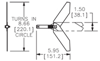
Dimensions are shown in inches with millimeter equivalent in brackets.
1.)
Standard Stainless Steel Three Vane Paddle: The most
popular of all paddles. For use with average weight
materials. |
|
2.) Large Stainless Steel Three Vane Paddle: Provides accurate level control for lightweight materials. P/N 1-4141 |
|
3.) Insertable* Stainless Steel,
Two Vane Collapsible Paddle: Provides low and high level
control for light to average weight materials. |
 |
4.)
Insertable* Stainless Steel, Scimitar Single Vane Paddle:
Provides low and high level control for light to average
weight materials. |
|
5.) Insertable*, Stainless Steel Single Vane Paddle: Provides low level control for average weight materials and low to high level control for heavy materials under 1-1/2 inch (40 mm) in diameter. P/N 1-4145 |
|
6.)
Stainless Steel, Two Vane Paddle: Provides low and
high level control for heavy materials under 1-1/2 inch
(40 mm) in diameter. P/N 1-4135 |
|
7.)
Stainless Steel Four Vane Paddle: For use with average
to heavy weight materials in low and high level control
installations. |
|
8.) Stainless Steel Triangular Arc Single Vane Paddle: Provides low and high level control for light to average weight materials. P/N 1-4144 |
|
9.) Ex-Flex Three-Ply 20 inch (508 mm) Belt Paddle: Provides low and high level control for heavy materials over 2 inch (50 mm) in diameter. Top mount only. P/N 1-4137 |
|
*Insertable paddles eliminate the need for a mounting plate. P/N 1-4161 and 1-4193 are insertable through either a half or full 1-1/4” or 1-1/2” coupling, that is welded to the bin wall. P/N 1-4145 is insertable through a half 1-1/4” or 1-1/2” coupling. |
|
|
|
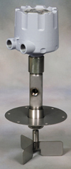
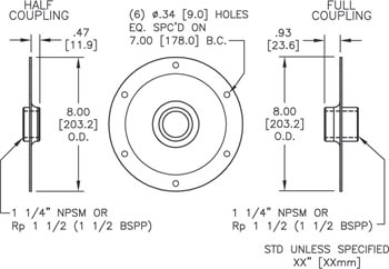
MOUNTING
PLATES
Mounting plates allow the paddle units to be mounted from the
outside of a vessel to curved or flat surfaces. All mounting
plates featured below mount via six bolts.
1.) Half Coupling Mounting Plate: For use in side mount installations. Available in powder coated carbon steel for general purpose applications and stainless steel for use in corrosive environments. Stainless Steel Plate: P/N 1-0112. Carbon Steel Plate: P/N 1-0101 for 1-1/4” NPT connection and P/N 1-0100 for 1-1/2” BSPT connection.
2.) Full Coupling Mounting Plate: For use in top mount installations where a shaft extension and shaft guards are required. Available in powder coated carbon steel for general purpose applications and stainless steel for use in corrosive environments. Stainless Steel Plate: P/N 1-0113. Carbon Steel Plate: P/N 1-0102 for 1-1/4" NPT connection and P/N 1-0115 for 1-1/2" BSPT connection.
3.) K-Flange Aluminum Mounting Plate: For flat surfaces or thin walled vessels where extra strength is required. Ideal for semi-corrosive environments, including out doors. P/N 1-3316.
Dimensions are shown in inches with millimeter
equivalent in brackets.
SHAFT
EXTENSIONS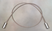
Many top mount installations require that the paddle extends
into the vessel to a predetermined level. Solid shaft extensions
are available in a variety of lengths up to 144 inches (3.6
m) to meet these demands. A flexible cable extension is also
available. This 6.5 foot (2.0 m) flexible extension can be
easily shortened in the field by the user. The use of the
flexible cable extension for lengths greater than 3 feet
(0.9m) requires the use of a guard to ensure proper activation
of the rotary paddle bin monitor.
SHAFT
GUARDS
Shaft guards are recommended for use with solid shaft extensions
to limit the movement caused by side loading that would otherwise
damage the working components of the paddle unit. Shaft guards
should be the same length as the extension and should always
be used when the extension meets or exceeds 18 inches (460
mm) in length.
Specifications
|
||||||||||||||||||||||||||||||||||||||||||||||||||||||||||||||||||||